
Table of Contents
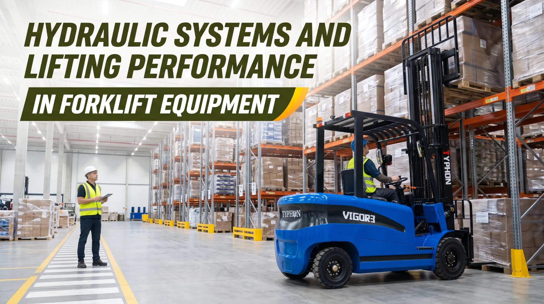
A forklift's lifting performance shows up in small moments throughout a shift. A loaded pallet rises smoothly to the top beam of a rack without hesitation. The mast tilts back just enough to cradle a tall load before travel. The forks lower under control and stop exactly where the operator intends. When the hydraulic system is healthy and well matched to the work, operators rarely think about it. When it isn't, problems appear quickly. Lifting turns slow under load, the mast chatters as it extends, the forks drift down while a load waits at height, or a side shifter barely responds by the end of the shift.
The hydraulic system powers nearly every lifting function on a forklift. It raises and lowers the carriage, tilts the mast, and drives attachments such as side shifters, fork positioners, clamps, and rotators. Its design determines how much force is available, how fast the mast moves, and how precisely the operator can place a load. Its condition determines whether that performance holds up day after day. Lifting performance still has a firm limit, though. A forklift's rated capacity comes from the complete machine, including its counterweight, mast structure, load center, and stability. Hydraulic force alone never decides how much a forklift can safely lift.
Main Components of a Forklift Hydraulic System
A forklift hydraulic system is a closed loop that stores oil, pressurizes it, directs it to the right cylinder, and returns it to storage. The reservoir, or hydraulic tank, holds the oil supply and gives it time to release air, shed heat, and settle contaminants. A suction strainer or filter protects the pump inlet, and a return filter cleans oil as it comes back from the system. A breather on the tank lets air move in and out as the oil level changes, ideally through a filter element that keeps dust and moisture out.
The pump turns mechanical power into hydraulic flow. Most forklifts use gear pumps because they are compact, durable, and economical. On internal combustion forklifts, the engine usually drives the pump directly, so pump output rises and falls with engine speed. On electric forklifts, a dedicated hydraulic pump motor drives the pump, and the controller adjusts motor speed according to how far the operator moves the lift lever. Many forklifts share pump output with the power steering circuit through a priority valve, which sends oil to steering first so the operator keeps steering control while lifting.
The control valve directs oil to each function. It contains a spool for lift, a spool for tilt, and additional sections for auxiliary functions on trucks equipped for attachments. Operators move these spools with mechanical levers, or with fingertip levers and joysticks on electro-hydraulic systems. A main relief valve caps maximum system pressure to protect the pump, hoses, and cylinders. Other valves add control and safety, including load-holding check valves, a tilt lock valve that prevents the mast from tilting forward when the truck is shut off, and a lowering control valve that limits how fast the forks can descend.
Cylinders turn hydraulic pressure into movement. Lift cylinders raise the mast and carriage, and on most forklifts they are single-acting. Oil pressure pushes them up, and the weight of the carriage, forks, and load brings them down as oil is metered back to the tank. Many lift cylinders also include a flow restrictor or velocity fuse at the base, which slows descent if a hose fails. Tilt cylinders are double-acting, using oil pressure in both directions to tilt the mast forward and back. Hoses, tubes, and fittings connect all of these components, and on the mast they route over sheaves or through hose reels so they can follow the mast as it extends.
Key takeaway: A forklift hydraulic system combines a reservoir, pump, control valve, lift and tilt cylinders, hoses, and protective valves. Each component plays a role in lifting performance, and the safety valves that hold, limit, and control movement are just as important as the parts that create it.
Hydraulic Flow and Lifting Speed
Where pressure creates force, flow creates speed. Flow is the volume of oil the pump delivers over time, usually measured in gallons per minute. The more oil that reaches a cylinder, the faster its piston moves. Cylinder speed equals flow divided by piston area, so a smaller cylinder moves faster than a larger one at the same flow.
The power source affects how flow is delivered. On an internal combustion forklift, the pump turns with the engine, so lifting speed rises as the operator increases engine speed. On an electric forklift, the controller varies pump motor speed in proportion to lever movement, which often gives smooth, precise control at low speed. Many electric trucks also allow technicians to adjust lift and tilt speed settings within the manufacturer's approved range. Those settings help match the truck to the application, such as reducing speed for fragile loads or crowded aisles.
More flow isn't automatically better. A system pushed beyond its design range can produce abrupt starts and stops, shift loads on the forks, and generate excess heat as unused oil passes over the relief valve. Lowering speed is just as important as lifting speed. Lowering control valves limit how fast the carriage can descend, protecting the load and the people nearby. Never modify, bypass, or remove these valves to speed up the work cycle. If lifting speed falls below the published figure, the cause is usually low oil, a restricted filter, cold oil, pump wear, or internal leakage, and the fix is diagnosis rather than adjustment.
Key takeaway: Flow sets lifting speed, while pressure sets force. Compare models using the manufacturer's published lift and lowering speeds, operate within approved speed settings, and treat a drop in lifting speed as a signal for inspection rather than adjustment.
Mast Design and Cylinder Performance
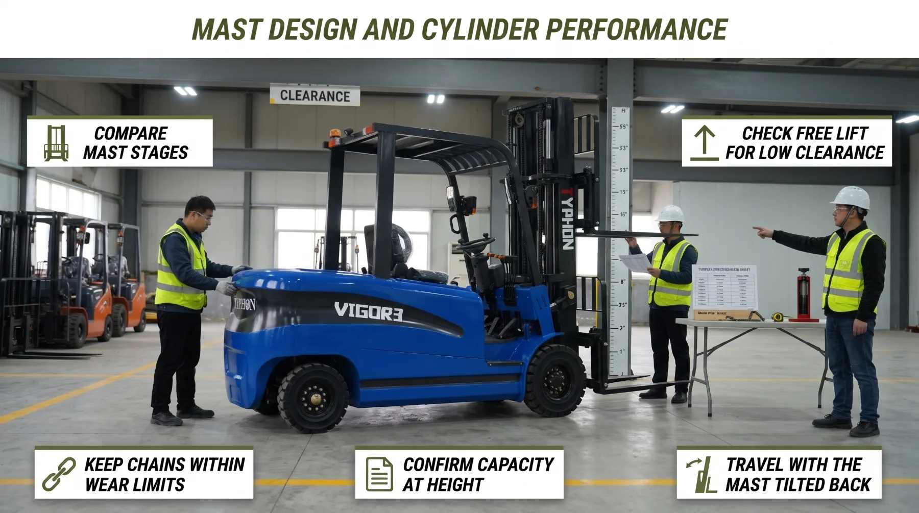
The mast converts cylinder movement into vertical lift. It consists of nested steel channels, rollers that guide each section, lift chains, sheaves, the carriage, and the lift cylinders that drive them. Mast design determines how high the forks can reach, how tall the truck stands when the mast is collapsed, and how much the operator can see through the mast.
Masts are described by the number of stages. A two-stage mast, often called a duplex, has two channel sections and suits general warehouse and loading dock work at moderate lift heights. A three-stage mast, or triplex, adds a third section to reach higher racking while keeping collapsed height low enough to pass through doorways and into trailers. Four-stage masts extend reach further for specialized applications. Each added stage brings more rollers, chains, and moving weight, and capacity at maximum height often decreases as a result.
Free lift is one of the most practical mast specifications. It describes how high the forks can rise before the mast's overall height begins to increase. Full free lift masts, common on triplex designs, use a dedicated free lift cylinder, usually mounted in the center of the mast. That cylinder raises the carriage first, then the main lift cylinders extend the outer sections. Full free lift matters inside trailers, containers, and buildings with low ceilings, where the mast must not strike the structure as the load rises. Because the free lift cylinder and main lift cylinders operate in sequence, a smooth transition between them is a good sign of a healthy mast. A noticeable jolt or hesitation at that point can indicate wear, misadjusted chains, or a hydraulic problem.
Lift chains deserve particular attention because they carry the load between the cylinders and the carriage. Leaf chains stretch gradually through wear at their pins, and manufacturers specify a maximum allowable elongation, often around 3 percent, beyond which the chain must be replaced. Chains on both sides should carry equal tension so the carriage rises level. Tilt cylinders complete the mast's motion, providing forward tilt for placing and picking up loads and back tilt for stabilizing them during travel. Operators should travel with the mast tilted back slightly and the load low, then tilt forward only when the load is positioned for placement.
When comparing forklifts, review maximum fork height, collapsed height, free lift, extended overall height, tilt angles, and capacity at the lift heights you actually use. Check visibility through the mast as well, since wide-view designs place cylinders and hoses behind the channels to open the operator's line of sight.
Key takeaway: Mast stages, free lift, chains, and tilt cylinders shape how hydraulic movement becomes usable lift. Compare collapsed height, free lift, and capacity at your working heights, keep chains within the manufacturer's wear limits, and watch for rough transitions between lift stages.
Hydraulic Attachments and Auxiliary Functions
Attachments extend a forklift's capabilities well beyond standard fork work. Side shifters move the carriage left and right for precise pallet placement. Fork positioners adjust fork spacing from the seat. Carton clamps, paper roll clamps, rotators, and push-pull units handle specialized loads without pallets. Each of these tools relies on auxiliary hydraulic functions, typically supplied through additional valve sections and hoses routed up the mast on a hose reel or sheave system.
Every attachment has specific hydraulic requirements. Flow affects how fast it moves, and pressure affects how hard it grips, pushes, or rotates. Clamp attachments are especially sensitive, since clamping force must be high enough to hold the load securely but not so high that it crushes cartons or damages paper rolls. Many clamp applications use pressure-regulating valves set for the product being handled. The attachment manufacturer's specifications define the correct flow, pressure, and connection arrangement, and the forklift must meet them.
Safe attachment use depends on correct installation and daily checks. Inspect auxiliary hoses for chafing where they move with the mast, confirm fittings are tight and leak-free, and check that mounting hooks and retaining hardware are secure. Before connecting or disconnecting any auxiliary hose, lower the attachment to the floor, shut down the truck, and relieve pressure as the manufacturer instructs. Test the attachment slowly and without a load after installation or service.
Key takeaway: Attachments require matching hydraulic flow, pressure, and connections, and they reduce net capacity by adding weight and shifting the load center forward. Use only approved attachments, confirm the data plate shows the revised capacity, and relieve pressure before handling auxiliary hoses.
Hydraulic Maintenance and Performance Monitoring
Consistent maintenance keeps lifting performance predictable and protects expensive components. Hydraulic oil condition sits at the center of that effort. Pumps, valve spools, and cylinder seals operate with tight clearances, and contaminated oil wears them quickly. Check the oil level during the daily inspection with the forks fully lowered and the mast vertical, since raised cylinders draw oil from the tank and give a false low reading. Top up only with the fluid the manufacturer specifies, using clean containers or a filtered transfer system. Replace hydraulic filters and the tank breather on the scheduled interval, and consider oil analysis for high-use fleets. Milky oil suggests water contamination, dark oil with a burnt smell points to overheating, and foam often means air is entering the system.
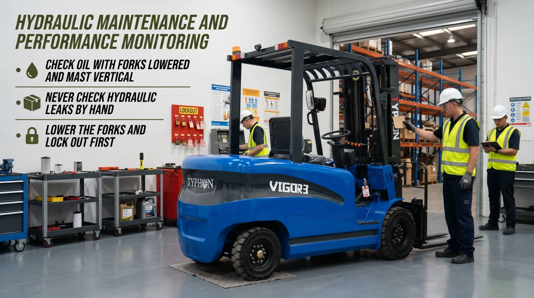
Daily inspections should cover the full lifting system. Look at hoses along the mast and carriage for abrasion, cracks, bulges, and wet spots. Check cylinder rods for scratches, pitting, and leaks at the seals. Inspect lift chains for stiff links, damage, uneven tension, and lubrication, and look over rollers, sheaves, and the carriage. Operate each function slowly through its full range before taking a load, and watch for warning signs. Slow lifting, jerky or chattering movement, forks that drift down while holding a load, a mast that tilts forward on its own, unusual pump noise, and rising oil temperature all indicate problems that need attention. Report them before the truck goes back into service, and remove the forklift from use if the problem affects lifting control or load holding.
Leak inspection must always be done safely. Never use your hand to search for a hydraulic leak. Fluid escaping through a pinhole under pressure can penetrate skin and cause an injection injury. The wound may look minor at first, but it's a medical emergency that requires immediate surgical treatment. Use a piece of cardboard or wood to locate a suspected leak, wear gloves and eye protection, and keep your face out of line with the leak point. If anyone is struck by escaping hydraulic fluid, get emergency medical care at once and tell medical staff it's a hydraulic injection injury.
Lockout protects technicians before any service. Park the forklift on a firm, level surface away from traffic, lower the forks fully to the floor, set the controls to neutral, and apply the parking brake. Shut down the truck and remove the key. On electric forklifts, disconnect the battery connector and identify the battery type, such as lead-acid or lithium-ion, before following the manufacturer's battery isolation and service procedures. Relieve hydraulic pressure as the manufacturer instructs, then apply your personal lock and tag according to your site's lockout procedure and verify isolation before starting work. If the mast or carriage must be raised for service, secure it with the manufacturer's approved blocking or chaining method. Never stand, walk, or work beneath raised forks or a raised carriage held only by hydraulics. Cylinder rebuilds, valve repairs, and relief valve checks should be handled by qualified technicians using the manufacturer's procedures, and only trained, authorized operators should run the truck. Record every inspection, fluid service, and repair so trends in performance are easy to spot.
Key takeaway: Clean oil, scheduled filter changes, and daily checks of hoses, cylinders, and chains keep lifting performance consistent. Check leaks with cardboard rather than your hands, lock out and lower the forks before service, and never work beneath a raised carriage held only by hydraulics.
Conclusion
Forklift lifting performance depends on the complete hydraulic system working together. The pump supplies flow, the control valve directs it, and lift and tilt cylinders turn pressure into controlled movement. Pressure and piston area create force, while flow sets lifting speed. The mast, with its stages, chains, and free lift design, converts cylinder movement into usable lift height. Attachments add capability but also add hydraulic demands and reduce net capacity. Through all of it, the data plate's rated capacity, based on the full truck and load center, defines the safe working limit.
Frequently Asked Questions
What does a forklift hydraulic system do?
The hydraulic system powers the forklift's lifting and positioning functions. It raises and lowers the carriage and forks, tilts the mast forward and back, and operates compatible attachments such as side shifters, fork positioners, clamps, and rotators. On many trucks, it also supplies the power steering circuit. Its main components include the reservoir, pump, control valve, lift and tilt cylinders, hoses, filters, and safety valves that hold loads and control lowering speed.
Does higher hydraulic flow increase forklift lifting capacity?
No. Flow controls how fast the cylinders move, so it affects lifting speed, not capacity. Pressure and piston area create lifting force, but even force doesn't define a safe load. Rated capacity depends on the complete truck, including counterweight, mast structure, load center, lift height, and any attachment. Always use the capacity shown on the forklift's data plate for its current configuration.
What causes slow forklift lifting?
Common causes include low hydraulic oil, a restricted filter or suction strainer, cold or contaminated oil, pump wear, internal leakage in a cylinder or valve, and air entering the system. On internal combustion trucks, low engine speed reduces pump flow, while electric trucks may slow lifting because of low battery charge or controller settings. Have a qualified technician diagnose the cause, and never adjust relief valve settings to compensate.
Can a forklift use any hydraulic attachment?
No. Each attachment must match the forklift's mounting, auxiliary hydraulic flow, pressure, and connection requirements. Attachments also reduce net capacity by adding weight and moving the load center forward. Use only attachments approved for the truck, confirm the data plate has been updated with the revised capacity, and train operators on how the attachment changes handling before putting it into service.
Equipment Guidance
Need help choosing equipment for your next job?
Contact KONSTRUCTZ support and get practical guidance before comparing machines, attachments, or jobsite requirements.Contact SupportReader Comments
Join the equipment discussion
Related Posts
No published comments yet.